Table of Contents
Project Details
Estimated Cost: £45
Time to complete: 45 minutes
Difficulty: Beginner
Soldering Required: No
Introduction
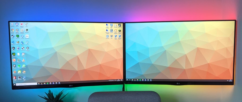
Bias lighting is a great way to add a little flair to your setup and can reduce eye strain when working in low light. This can be achieved in many ways but the one that I think looks best are rear mounted LED strips. Specifically, individually addressable LED strips in which the colors can be controlled on a per-LED basis allowing you to create advanced effects like shown below.
Parts Required
Smart Home Platform (Optional)
This guide goes through setting up the lighting with effects and other cool stuff. A smart home platform is not required to control the LEDs, but if you use HomeAssistant, WLED is tightly integrated and you can use it for your automations like I did!
In another article, I go over how to utilize HomeAssistant and a few door sensors to make these lights work as an intruder alarm for my house! You can find a link to that article at the top of this post
Monitor(s)
Obviously you will need something to add the bias lighting to. Whether you are using one monitor or two, it won’t matter as I will cover scenarios for both. You can even do this to your TV, but for that, I would recommend using Hyperion.
LED Strips
I would recommend using a WS2812B LED strip at 30 LEDs per meter. You could go for 60 LEDs per meter but it won’t make your bias lighting look that much greater.
For my setup, I have 78 LEDs at 30 LEDs per meter that go around 2 x 24″ monitors which works out to be 2.33 meters in length. I had some left overs from old projects which was perfect for this.
I have used BTF LED strips for all my projects and think they are great (not sponsored). However, if you can find a cheaper alternative WS2812B LED strip, you may find that colours may not match other match LED strip manufacturers when compared side-by-side.
Other LED strips
If you want to know more about what different strips do and what is best for your project, I would recommend watching this video by Rob from The Hook Up to learn which one you need. However, be sure to check it’s compatible with WLED (which I am using for this project) here: https://github.com/Aircoookie/WLED/wiki/Compatible-hardware#addressable-led-strips
LED strip connectors
It’s really handy to have a few 3 pin LED strip connectors laying around. You never know when you need them and we use a connector in this project to join the 2 seperate monitor strips together.
ESP8266 Microcontroller – NodeMCU
To control the LEDs, we need a Microcontroller. For this project, I am using a NodeMCU ESP8266 which costs around £6 from Amazon. However, WLED supports a wide range of controllers and you can find all the compatible boards here: https://github.com/Aircoookie/WLED/wiki/Compatible-hardware#esp8266esp32-boards
Wiring Prep
LED Strip Connector
Before we get into connecting everything up, I have made a change to the LED strip connector so it can natively connect to the NodeMCU without soldering.
Note: This step is optional, but because I want to make this a solderless project, I have made an easy adjustment that you can use
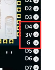
On the NodeMCU, we have the following pins available next to each other in order: D4 (Data 4), 3 volts and Ground.
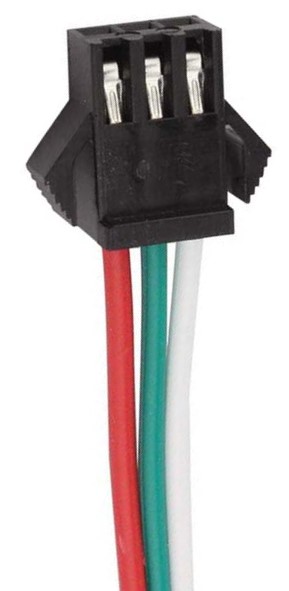
Now, a normal LED strip connector has the following connections (in order): Red (5 volts), Green (Data), White (Ground).
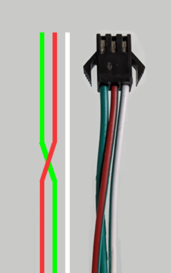
I have swapped over the data (green) and power (red) cables within the 3 pin LED strip connector.
This can be accomplished by pushing in the metal clips holding the wires inside the connector and pulling out both the green and red wires. Now, reinsert the cables, but swap the positions so that it matches the diagram.
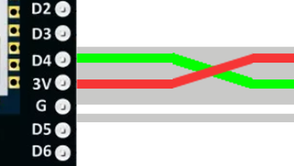
This then allows me to plug the female LED connector head into the NodeMCU making sure that: Green goes to D4 (Data 4), Red goes to 3V (3 Volts) and White goes to ground.
Then, If I ever wanted to swap the NodeMCU out or do work on the LEDs, detaching these would be easy!
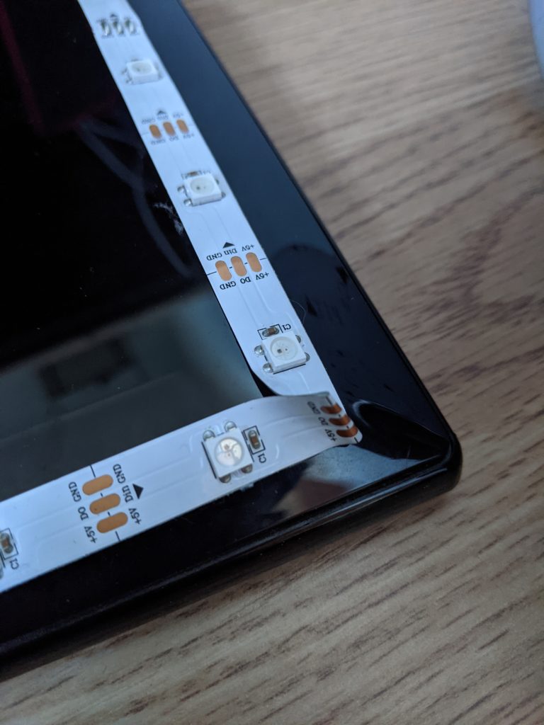
Attaching the LED strips
Attaching the LED strips isn’t as hard as you think. With a few connectors and careful bends, you can get it done in no time. Before you take off the adhesive backing, I would recommend checking how many LEDs you are going to go across and down. I was very particular in the placement to get them centered and it paid off. I would also keep a note of how many LEDs in total you are using from start to finish. You will need this later.
Corners
There are a lot of methods of doing corners, but for this project I am just going to force the LEDs into a 90° angle ensuring to allow the LED strip bend.
This is by no means the best way of doing this but it’s fine for this project. Other methods include corner connectors and soldering, so just do what you are comfortable with
Positioning
Once you are ready to stick the LEDs on, find a starting point and go around the edge of one of the monitors until you reach the end. Using the diagram below for reference, I started from the green circle and went around the monitor.
The red section shows LEDs that will not be used. I didn’t want to cut my LED strip short just in case I re-use these for a different project, so decided to stick them on and disable them in WLED later.
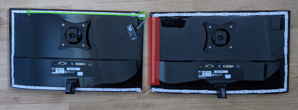
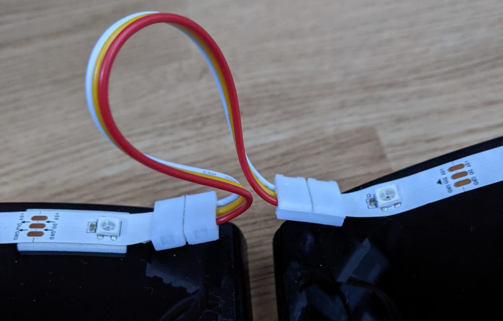
Using an LED connector, I then joined the 2 monitor strips so that I still have some freedom when adjusting my monitors.
At the top of this post, you can find an Amazon link to the LED connector from a pack I used for this.
However, these connectors can be tempremental as the metal clips don’t always put enough pressure on the LED strip copper pads to create a solid connection. See my FAQs below if you run into this issue
For a single display
As per the above diagram, do the same as what is on the left monitor, but continue the LED strip back to the starting point. Simpe!
Flashing the NodeMCU
Now we have the LEDs mounted, let’s install WLED onto the NodeMCU.
- Download the latest 64 bit version of esphome-flasher from GitHub: https://github.com/esphome/esphome-flasher/releases
- Additionally, download the latest WLED binary from GitHub. If you are using a NodeMCU, choose the file ending in “_ESP8266.bin”: https://github.com/Aircoookie/WLED/releases/latest
- Connect the NodeMCU to your PC using a MicroUSB cable and open esphome-flasher x64.
- Choose the Serial Port that has your NodeMCU connected. If there are multiple listed, unplug the NodeMCU, click the refresh button and see which one disappeared. Then, plug the NodeMCU back in, click refresh and choose the relevant COM port.
- Under “Firmware”, browse and select the WLED binary you just downloaded.
- Click “Flash ESP” and after a minute or so, you will see the message “Done! Flashing is complete!”. You can keep the NodeMCU plugged in so we can do the initial setup next.
Note: If you notice that your LEDs are on but some are off, don’t panic, this is normal. We can fix this in WLED later.
Initial setup of WLED
Now we have flashed the NodeMCU, we must now configure it to connect to our WiFi network. To do that, on your phone, look for a WiFi network called WLED-AP. Join that network with the password wled1234. You will then be presented with an option to “Sign into the network” which you should tap on. This will then bring you to the WLED WiFi setup page.
The only fields I needed to change were “Network Name” to be the WiFi network name for my house, and “Network password” which is the password for my WiFi network. Before clicking “Save & Connect”, make a note of the name of the device under “mDNS address”. This is the web address you can use to access the WLED interface if you don’t know the IP address.
I would also recommend checking “Hide AP name” under “Configure Access Point” to anyone else trying to connect in the future.
Once you are happy with the settings, click “Save & Connect”. Your phone should then get disconnected from the WLED-AP network. We can now do the rest from a computer if you wish. The NodeMCU will then connect to the WiFi network you specified.
Accessing WLED
On your computer, open a web browser and enter http://{mDNS Name} (not https). This should take you to the WLED interface. If you are having trouble getting to that page, I would try using the WLED mobile app. You can download it for Android and iOS and it can scan your network to find instances of WLED and then control the effects.

All done!
Well done! You have successfully created Bias lighting using WLED. Have a play with WLED and have fun playing with the new effects. If you run into issues, take a read of the FAQs below before you write a comment.
FAQs
I can’t access the WLED page
See above in the article where I mention about using the WLED mobile app. This has auto-discovery features to help access your WLED instance.
Not all of my LEDs are on / Too many of my LEDs are on
Don’t panic! WLED allows you to limit the number of LEDs in your setup so that it can turn the rest of to conserve energy and provide more accurate colors and brightness to the LEDs that require it.
To change this, go to the WLED interface and go to Config > LED Preferences. Now, take the number of LEDs that surround your monitor(s), and enter that number in the “Total LED count”. Click “Save” and the LEDs should now be correct.
When I choose a color, the LEDs are different
Different LED manufactures choose to use different arrangement of the RGB(W) channels. If you go to the WLED interface and go to Config > LED Preferences and find “Color Order”, you can change the order in which the channels are represented on your strip. This information should be displayed on the website you purchased them from but if not, you can just try all 6 options until the colors are what you choose them to be
The colors aren’t accurate
This is due to the power supply you are using. For this project, since we are using a small number of LEDs (presumably), this issue shouldn’t be a problem. Personally, I am powering my NodeMCU using my PC’s USB port which is 500mA. (0.5 amps). However, if you are trying to produce a color that requires all Red, Green and Blue channels to be on, but may not supplying enough amps to your NodeMCU to pass through to the LEDs.
Try find a 5v USB wall charger laying around that has an “Output” of 2 amps or more. That should help.
My LEDs aren’t turning on at all
This could be a number of problems. First, make sure that the NodeMCU is getting power. You can verify this by the blue LED on the device. Secondly, ensure that the LED connector is connected to the correct pins as mentioned earlier in the article.
My LEDs are not turning on past the LED connector
LED connectors are really handy but from my experience, fail quite often. This is due to poor pressure being put on the LED connections. A fix I use quite often is to put a few layers of masking tape on the back of the LED strip where it goes into the LED connector. This raises the LED connectors up slightly and when the clip is closed, puts more pressure on the connections, creating a tighter bond.
Further help
If you have followed this guide but are having issues with your setup, feel free to get in touch using the comments below. I will do my best to help resolve your problem.